#31. Channel Tunnel
Eurotunnel – Superstructures – Discovery Channel
 Channel Tunnel Location: English Channel Architect: Year: 1994
Not only does the Channel Tunnel provide fast service between London and Paris, it is also the single longest undersea tunnel in the world. A healthy portion of its 31.3 miles sits under its namesake body of water. The total length also makes the Channel Tunnel the second longest rail tunnel ever completed.
The Channel Tunnel (French: Le tunnel sous la Manche; also referred to as the Chunnel) is a 50.5-kilometre (31.4 mi) rail tunnel linking Folkestone, Kent, in the United Kingdom with Coquelles, Pas-de-Calais, near Calais in northern France beneath the English Channel at the Strait of Dover. At its lowest point, it is 75 m (250 ft) deep. At 37.9 kilometres (23.5 mi), the tunnel has the longest undersea portion of any tunnel in the world, although the Seikan Tunnel in Japan is both longer overall at 53.85 kilometres (33.46 mi) and deeper at 240 metres (790 ft) below sea level.
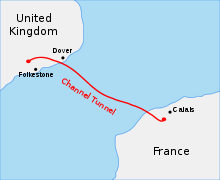 Map of the Channel Tunnel
The tunnel carries high-speed Eurostar passenger trains, Eurotunnel Shuttle roll-on/roll-off vehicle transport—the largest in the world—and international rail freight trains. The tunnel connects end-to-end with the LGV Nord and High Speed 1 high-speed railway lines.
Ideas for a cross-Channel fixed link appeared as early as 1802, but British political and press pressure over compromised national security stalled attempts to construct a tunnel. The eventual successful project, organised by Eurotunnel, began construction in 1988 and opened in 1994. At £4.650 billion, the project came in 80% over its predicted budget. Since its construction, the tunnel has faced several problems. Fires have disrupted operation of the tunnel. Illegal immigrants and asylum seekers have attempted to use the tunnel to enter the UK, causing a minor diplomatic disagreement over the siting of the Sangatte refugee camp, which was eventually closed in 2002.
Origins – Proposals and attempts
| 1802 | Albert Mathieu put forward a cross-Channel tunnel proposal. |
| 1875 | The Channel Tunnel Company Ltd began preliminary trials |
| 1882 | The Abbot’s Cliff heading had reached 897 yards (820 m) and that at Shakespeare Cliff was 2,040 yards (1,870 m) in length |
| January 1975 | A UK–France government backed scheme that started in 1974 was cancelled |
| February 1986 | The Treaty of Canterbury was signed allowing the project to proceed |
| June 1988 | First tunnelling commenced in France |
| December 1988 | UK TBM commenced operation |
| December 1990 | The service tunnel broke through under the Channel |
| May 1994 | The tunnel was formally opened by Queen Elizabeth II and President Mitterrand |
| Mid-1994 | Freight and passenger trains commenced operation |
| November 1996 | A fire in a lorry shuttle severely damaged the tunnel |
| November 2007 | High Speed 1, linking London to the tunnel, opened |
| September 2008 | Another fire in a lorry shuttle severely damaged the tunnel |
| December 2009 | Eurostar trains stranded in the tunnel due to melting snow affecting the trains’ electrical hardware |
In 1802, Albert Mathieu, a French mining engineer, put forward a proposal to tunnel under the English Channel, with illumination from oil lamps, horse-drawn coaches, and an artificial island mid-Channel for changing horses.
In the 1830’s, Aimé Thomé de Gamond, a Frenchman, performed the first geological and hydrographical surveys on the Channel, between Calais and Dover. Thomé de Gamond explored several schemes and, in 1856, he presented a proposal to Napoleon III for a mined railway tunnel from Cap Gris-Nez to Eastwater Point with a port/airshaft on the Varne sandbank at a cost of 170 million francs, or less than £7 million.
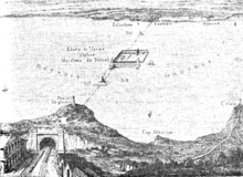 Thomé de Gamond’s plan of 1856 for a cross-Channel link, with a port/airshaft on the Varne sandbank mid-Channel
In 1865, a deputation led by George Ward Hunt proposed the idea of a tunnel to the Chancellor of the Exchequer of the day,William Ewart Gladstone.
After 1867, William Low and Sir John Clarke Hawkshaw promoted ideas, but none were implemented. An official Anglo-French protocol was established in 1876 for a cross-Channel railway tunnel. In 1881, the British railway entrepreneur Sir Edward Watkin and Alexandre Lavalley, a French Suez Canal contractor, were in the Anglo-French Submarine Railway Company that conducted exploratory work on both sides of the Channel. On the English side a 2.13-metre (7 ft) diameter Beaumont-English boring machine dug a 1,893-metre (6,211 ft) pilot tunnel from Shakespeare Cliff. On the French side, a similar machine dug 1,669 m (5,476 ft) from Sangatte. The project was abandoned in May 1882, owing to British political and press campaigns advocating that a tunnel would compromise Britain’s national defences. These early works were encountered more than a century later during the TML project.
In 1919, during the Paris Peace Conference, the British prime minister,David Lloyd George, repeatedly brought up the idea of a Channel tunnel as a way of reassuring France about British willingness to defend against another German attack. The French did not take the idea seriously and nothing came of Lloyd George’s proposal.
In 1929 there was another proposal but nothing came of this discussion and the idea was shelved. Proponents estimated construction to be about US$150 million. The engineers had addressed the concerns of both nations’ military leaders by designing two sumps—one near the coast of each country—that could be flooded at will to block the tunnel. This design feature did not override the concerns of both nations’ military leaders, and other concerns about hordes of undesirable tourists who would disrupt English habits of living. Military fears continued during World War II. After the fall of France, as Britain prepared for an expected German invasion, a Royal Navy officer in the Directorate of Miscellaneous Weapons Development calculated that Hitler could use slave labor to build two Channel tunnels in 18 months. The estimate caused rumours that Germany had already begun digging.
In 1955, defence arguments were accepted to be irrelevant because of the dominance of air power, and both the British and French governments supported technical and geological surveys. A detailed geological survey was carried out in 1964–65. Construction work commenced on both sides of the Channel in 1974, a government-funded project using twin tunnels on either side of a service tunnel, with capability for car shuttle wagons. In January 1975, to the dismay of the French partners, the British government cancelled the project. The government had changed to the Labour Party and there was uncertainty about EEC membership, cost estimates had ballooned to 200% and the national economy was troubled. By this time the British tunnel boring machine was ready and the Ministry of Transport was able to do a 300 m (980 ft) experimental drive. This short tunnel was reused as the starting and access point for tunnelling operations from the British side.
In 1979, the “Mouse-hole Project” was suggested when the Conservatives came to power in Britain. The concept was a single-track rail tunnel with a service tunnel, but without shuttle terminals. The British government took no interest in funding the project, but Margaret Thatcher, the prime minister, said she had no objection to a privately funded project. In 1981 Thatcher and François Mitterrand, the French president, agreed to set up a working group to look into a privately funded project, and in April 1985 promoters were formally invited to submit scheme proposals. Four submissions were shortlisted:
- a rail proposal based on the 1975 scheme presented by Channel Tunnel Group/France–Manche (CTG/F–M),
- Eurobridge: a 4.5 km (2.8 mi) span suspension bridge with a roadway in an enclosed tube
- Euroroute: a 21 km (13 mi) tunnel between artificial islands approached by bridges, and
- Channel Expressway: large diameter road tunnels with mid-channel ventilation towers.
The cross-Channel ferry industry protested under the name “Flexilink”. In 1975 there was no campaign protesting against a fixed link, with one of the largest ferry operators (Sealink) being state-owned. Flexilink continued rousing opposition throughout 1986 and 1987. Public opinion strongly favoured a drive-through tunnel, but ventilation issues, concerns about accident management, and fear of driver mesmerisation led to the only shortlisted rail submission, CTG/F-M, being awarded the project.
Arrangement
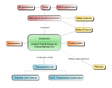 A block diagram describing the organisation structure used on the project. Eurotunnel is the central organisation for construction and operation (via a concession) of the tunnel
The British Channel Tunnel Group consisted of two banks and five construction companies, while their French counterparts, France–Manche, consisted of three banks and five construction companies. The role of the banks was to advise on financing and secure loan commitments. On 2 July 1985, the groups formed Channel Tunnel Group/France–Manche (CTG/F–M). Their submission to the British and French governments was drawn from the 1975 project, including 11 volumes and a substantial environmental impact statement.
The design and construction was done by the ten construction companies in the CTG/F-M group. The French terminal and boring from Sangatte was undertaken by the five French construction companies in the joint venture group GIE Transmanche Construction. The English Terminal and boring from Shakespeare Cliff was undertaken by the five British construction companies in the Translink Joint Venture. The two partnerships were linked by TransManche Link (TML), a bi-national project organisation. The Maître d’Oeuvre was a supervisory engineering body employed by Eurotunnel under the terms of the concession that monitored project activity and reported back to the governments and banks.
In France, with its long tradition of infrastructure investment, the project garnered widespread approval. In April the French National Assembly gave unanimous support and, in June 1987, after a public inquiry, the Senate gave unanimous support. In Britain, select committees examined the proposal, making history by holding hearings away from Westminster, in Kent. In February 1987, the third reading of the Channel Tunnel Bill took place in the House of Commons, and was carried by 94 votes to 22. The Channel Tunnel Act gained Royal assent and passed into law in July. Parliamentary support for the project came partly from provincial members of Parliament on the basis of promises of regional Eurostar through train services that never materialised; the promises were repeated in 1996 when the contract for construction of the Channel Tunnel Rail Link was awarded.
The tunnel is a build-own-operate-transfer (BOOT) project with a concession. TML would design and build the tunnel, but financing was through a separate legal entity, Eurotunnel. Eurotunnel absorbed CTG/F-M and signed a construction contract with TML, but the British and French governments controlled final engineering and safety decisions, now in the hands of the Channel Tunnel Safety Authority. The British and French governments gave Eurotunnel a 55- (later 65-) year operating concession to repay loans and pay dividends. A Railway Usage Agreement was signed between Eurotunnel, British Rail and the Société Nationale des Chemins de fer Français guaranteeing future revenue in exchange for the railways obtaining half of the tunnel’s capacity.
Private funding for such a complex infrastructure project was of unprecedented scale. An initial equity of £45 million was raised by CTG/F-M, increased by £206 million private institutional placement, £770 million was raised in a public share offer that included press and television advertisements, a syndicated bank loan and letter of credit arranged £5 billion. Privately financed, the total investment costs at 1985 prices were £2600 million. At the 1994 completion actual costs were, in 1985 prices, £4650 million: an 80% cost overrun. The cost overrun was partly due to enhanced safety, security, and environmental demands. Financing costs were 140% higher than forecast.
Construction
Working from both the English side and the French side of the Channel, eleven tunnel boring machines cut through chalk marl to construct two rail tunnels and a service tunnel. The vehicle shuttle terminals are at Cheriton (part of Folkestone) and Coquelles, and are connected to the English M20 and French A16 motorways respectively).
Tunnelling commenced in 1988, and the tunnel began operating in 1994. In 1985 prices, the total construction cost was £4.650 billion (equivalent to £12 billion today), an 80% cost overrun. At the peak of construction 15,000 people were employed with daily expenditure over £3 million. Ten workers, eight of them British, were killed during construction between 1987 and 1993, most in the first few months of boring.
Completion
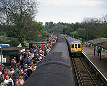 Class 319 EMUs ran excursions trips into the tunnel from Sandling railway stationon 7 May 1994, the first passenger trains to do so
A two-inch (50-mm) diameter pilot hole allowed the service tunnel to break through without ceremony on 30 October 1990. On 1 December 1990, Englishman Graham Fagg and Frenchman Phillippe Cozette broke through the service tunnel with the media watching. Eurotunnel completed the tunnel on time, and the tunnel was officially opened one year later than originally planned by Queen Elizabeth II and the French president, François Mitterrand, in a ceremony held in Calais on 6 May 1994. The Queen travelled through the tunnel to Calais on a Eurostar train, which stopped nose to nose with the train that carried President Mitterrand from Paris. Following the ceremony President Mitterrand and the Queen travelled on Le Shuttle to a similar ceremony in Folkestone. A full public service did not start for several months.
The Channel Tunnel Rail Link (CTRL), now called High Speed 1, runs 69 miles (111 km) from St Pancras railway station in London to the tunnel portal at Folkestone in Kent. It cost £5.8 billion. On 16 September 2003 the prime minister, Tony Blair, opened the first section of High Speed 1, from Folkestone to north Kent. On 6 November 2007 the Queen officially opened High Speed 1 and St Pancras International station, replacing the original slower link to Waterloo International railway station. On High Speed 1 trains travel at up to 300 km/h (186 mph), the journey from London to Paris taking 2 hours 15 minutes, to Brussels 1 hour 51 minutes.
In 1994, the American Society of Civil Engineers elected the tunnel as one of the seven modern Wonders of the World. In 1995, the American magazine Popular Mechanics published the results.
Engineering
 The Channel Tunnel exhibit at theNational Railway Museum in York, England, showing the circular cross section of the tunnel with the overhead line powering a Eurostar train. Also visible is the segmented tunnel lining
Surveying undertaken in the 20 years before construction confirmed earlier speculations that a tunnel could be bored through a chalk marl stratum. The chalk marl was conducive to tunnelling, with impermeability, ease of excavation and strength. On the English side the chalk marl ran along the entire length of the tunnel, but on the French a length of 5 kilometres (3 mi) had variable and difficult geology. The tunnel consists of three bores: two 7.6-metre (25 ft) diameter rail tunnels, 30 metres (98 ft) apart, 50 kilometres (31 mi) in length with a 4.8-metre (16 ft) diameter service tunnel in between. There are also cross-passages and piston relief ducts. The service tunnel was used as a pilot tunnel, boring ahead of the main tunnels to determine the conditions. English access was provided at Shakespeare Cliff, French access from a shaft at Sangatte. The French side used five tunnel boring machines (TBMs), the English side six. The service tunnel uses Service Tunnel Transport System (STTS) and Light Service Tunnel Vehicles (LADOGS). Fire safety was a critical design issue.
Between the portals at Beussingue and Castle Hill the tunnel is 50.5 kilometres (31 mi) long, with 3.3 kilometres (2 mi) under land on the French side and 9.3 kilometres (6 mi) on the UK side, and 37.9 kilometres (24 mi) under sea. It is the second-longest rail tunnel in the world, behind the Seikan Tunnel in Japan, but with the longest under-sea section. The average depth is 45 metres (148 ft) below the seabed. On the UK side, of the expected 5 million cubic metres (6.5×10⁶ cu yd) of spoil approximately 1 million cubic metres (1.3×10⁶ cu yd) was used for fill at the terminal site, and the remainder was deposited at Lower Shakespeare Cliff behind a seawall, reclaiming 74 acres (30 ha) of land. This land was then made into the Samphire Hoe Country Park. Environmental impact assessment did not identify any major risks for the project, and further studies into safety, noise, and air pollution were overall positive. However, environmental objections were raised over a high-speed link to London.
Geology
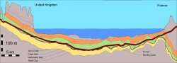 Geological profile along the tunnel as constructed. For most of its length the tunnel bores through a chalk marl stratum (layer)
Successful tunnelling required a sound understanding of the topography and geology and the selection of the best rock strata through which to tunnel. The geology generally consists of northeasterly dipping Cretaceous strata, part of the northern limb of the Wealden-Boulonnais dome. Characteristics include:
- Continuous chalk on the cliffs on either side of the Channel containing no major faulting, as observed by Verstegan in 1698
- Four geological strata, marine sediments laid down 90–100 million years ago; pervious upper and middle chalk above slightly pervious lower chalk and finally impermeable Gault Clay. A sandy stratum, glauconitic marl (tortia), is in between the chalk marl and gault clay
- A 25–30-metre (82–98 ft) layer of chalk marl (French: craie bleue) in the lower third of the lower chalk appeared to present the best tunnelling medium. The chalk has a clay content of 30–40% providing impermeability to groundwater yet relatively easy excavation with strength allowing minimal support. Ideally the tunnel would be bored in the bottom 15 metres (49 ft) of the chalk marl, allowing water inflow from fractures and joints to be minimised, but above the gault clay that would increase stress on the tunnel lining and swell and soften when wet.
On the English side, the strata dip is less than 5°; on the French side this increases to 20°. Jointing and faulting are present on both sides. On the English side, only minor faults of displacement less than 2 metres (7 ft) exist; on the French side, displacements of up to 15 metres (49 ft) are present owing to the Quenocs anticlinal fold. The faults are of limited width, filled with calcite, pyrite and remoulded clay. The increased dip and faulting restricted the selection of route on the French side. To avoid confusion, microfossil assemblages were used to classify the chalk marl. On the French side, particularly near the coast, the chalk was harder, more brittle and more fractured than on the English side. This led to the adoption of different tunnelling techniques on the two sides.
The Quaternary undersea valley Fosse Dangaered, and Castle Hill landslip at the English portal, caused concerns. Identified by the 1964–65 geophysical survey, the Fosse Dangaered is an infilled valley system extending 80 metres (262 ft) below the seabed, 500 metres (1,640 ft) south of the tunnel route in mid-channel. A 1986 survey showed that a tributary crossed the path of the tunnel, and so the tunnel route was made as far north and deep as possible. The English terminal had to be located in the Castle Hill landslip, which consists of displaced and tipping blocks of lower chalk, glauconitic marl and gault debris. Thus the area was stabilised by buttressing and inserting drainage adits. The service tunnel acted as a pilot tunnel preceding the main tunnels, so that the geology, areas of crushed rock, and zones of high water inflow could be predicted. Exploratory probing took place in the service tunnel, in the form of extensive forward probing, vertical downward probes and sideways probing.
Surveying
Marine soundings and samplings by Thomé de Gamond were carried out during 1833–67, establishing the seabed depth at a maximum of 55 metres (180 ft) and the continuity of geological strata (layers). Surveying continued over many years, with 166 marine and 70 land-deep boreholes being drilled and over 4,000-line-kilometres of marine geophysical survey completed. Surveys were undertaken in 1958–1959, 1964–1965, 1972–1974 and 1986–1988.
The surveying in 1958–59 catered for immersed tube and bridge designs as well as a bored tunnel, and thus a wide area was investigated. At this time marine geophysics surveying for engineering projects was in its infancy, with poor positioning and resolution from seismic profiling. The 1964–65 surveys concentrated on a northerly route that left the English coast at Dover harbour; using 70 boreholes, an area of deeply weathered rock with high permeability was located just south of Dover harbour.
Given the previous survey results and access constraints, a more southerly route was investigated in the 1972–73 survey and the route was confirmed to be feasible. Information for the tunnelling project also came from work before the 1975 cancellation. On the French side at Sangatte a deep shaft with adits was made. On the English side at Shakespeare Cliff, the government allowed 250 metres (820 ft) of 4.5-metre (15 ft) diameter tunnel to be driven. The actual tunnel alignment, method of excavation and support were essentially the same as the 1975 attempt. In the 1986–97 survey, previous findings were reinforced and the nature of the gault clay and the tunnelling medium (chalk marl that made up 85% of the route) were investigated. Geophysical techniques from the oil industry were employed.
Tunnelling
 Typical tunnel cross section, with the service tunnel between twin rail tunnels. Shown linking the rail tunnels is a piston relief duct, necessary to manage pressure changes due to the movement of trains
Tunnelling was a major engineering challenge, with the only precedent being the undersea Seikan Tunnel in Japan. A serious risk with underwater tunnels is major water inflow due to the water pressure from the sea above under weak ground conditions. The tunnel also had the challenge of time: being privately funded, early financial return was paramount.
The objective was to construct two 7.6-metre (25 ft) diameter rail tunnels, 30 metres (98 ft) apart, 50 kilometres (31 mi) in length; a 4.8-metre (16 ft) diameter service tunnel between the two main tunnels; pairs of 3.3-metre (11 ft) diameter cross-passages linking the rail tunnels to the service tunnel at 375-metre (1,230 ft) spacing; piston relief ducts 2-metre (7 ft) diameter connecting the rail tunnels at 250-metre (820 ft) spacing; two undersea crossover caverns to connect the rail tunnels. The service tunnel always preceded the main tunnels by at least 1 kilometre (0.6 mi) to ascertain the ground conditions. There was plenty of experience with tunnelling through chalk in the mining industry. The undersea crossover caverns were a complex engineering problem. The French cavern was based on the Mount Baker Ridge freeway tunnel in the US. The UK cavern was dug from the service tunnel ahead of the main tunnels to avoid delay.
Precast segmental linings in the main TBM drives were used, but different solutions were used on the two sides. On the French side, neoprene and grout sealed bolted linings made of cast iron or high-strength reinforced concrete were used. On the English side, the main requirement was for speed and bolting of cast-iron lining segments was only carried out in areas of poor geology. In the UK rail tunnels, eight lining segments plus a key segment were used; on the French side, five segments plus a key segment. On the French side, a 55-metre (180 ft) diameter 75-metre (246 ft) deep grout-curtained shaft at Sangatte was used for access. On the English side, a marshalling area was 140 metres (459 ft) below the top of Shakespeare Cliff, and the New Austrian Tunnelling method (NATM) was first applied in the chalk marl here. On the English side, the land tunnels were driven from Shakespeare Cliff, the same place as the marine tunnels, not from Folkestone. The platform at the base of the cliff was not large enough for all of the drives and, despite environmental objections, tunnel spoil was placed behind a reinforced concrete seawall, on condition of placing the chalk in an enclosed lagoon to avoid wide dispersal of chalk fines. Owing to limited space, the precast lining factory was on the Isle of Grain in the Thames estuary.
On the French side, owing to the greater permeability to water, earth pressure balance TBMs with open and closed modes were used. The TBMs were of a closed nature during the initial 5 kilometres (3 mi), but then operated as open, boring through the chalk marl stratum. This minimised the impact to the ground and allowed high water pressures to be withstood, and it also alleviated the need to grout ahead of the tunnel. The French effort required five TBMs: two main marine machines, one main land machine (the short land drives of 3 km (2 mi) allowed one TBM to complete the first drive then reverse direction and complete the other), and two service tunnel machines. On the English side, the simpler geology allowed faster open-faced TBMs. Six machines were used, all commenced digging from Shakespeare Cliff, three marine-bound and three for the land tunnels. Towards the completion of the undersea drives, the UK TBMs were driven steeply downwards and buried clear of the tunnel. These buried TBMs were then used to provide an electrical earth. The French TBMs then completed the tunnel and were dismantled. A 900 mm (35 in) gauge railway was used on the English side during construction.
In contrast to the English machines, which were given alphanumeric names, the French tunnelling machines were all named after women: Brigitte, Europa, Catherine, Virginie, Pascaline, Séverine.
Railway design
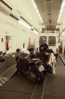 Interior of Eurotunnel Shuttle, a vehicle shuttle train. The largest railway wagons in the world, the shuttle trains transport vehicles between terminals at either end of the tunnel
Communications
There are three communication systems: concession radio (CR) for mobile vehicles and personnel within Eurotunnel’s Concession (terminals, tunnels, coastal shafts); track-to-train radio (TTR) for secure speech and data between trains and the railway control centre; Shuttle internal radio (SIR) for communication between shuttle crew and to passengers over car radios. This service was discontinued within one year of opening because of drivers’ difficulty setting their radios to the correct frequency (88.8 MHz).
Power supply
All tunnel services run on electricity, shared equally from English and French sources. Power is delivered to the locomotives via an overhead line (catenary) at 25 kV 50 Hz.
The traditional railway south of London used initially uses a 750 V DC third rail to deliver electricity, but since the opening of High Speed 1 there is no need to use the third rail system. High Speed 1, the tunnel and the route to Paris has power provided via overhead catenary at 25 kV 50 Hz. The railways on “classic” lines in Belgium are also electrified by overhead wires, but at 3000 V DC.
Signalling
| [hide] Channel Tunnel / Eurotunnel | ||||||||||||||||||||||||||||||||||||||||||||||||||||||||||||||||||||||||||||||||||
|---|---|---|---|---|---|---|---|---|---|---|---|---|---|---|---|---|---|---|---|---|---|---|---|---|---|---|---|---|---|---|---|---|---|---|---|---|---|---|---|---|---|---|---|---|---|---|---|---|---|---|---|---|---|---|---|---|---|---|---|---|---|---|---|---|---|---|---|---|---|---|---|---|---|---|---|---|---|---|---|---|---|---|
|
||||||||||||||||||||||||||||||||||||||||||||||||||||||||||||||||||||||||||||||||||
A cab signalling system gives information directly to train drivers on a display. There is a train protection system that stops the train if the speed exceeds that indicated on the in-cab display. TVM430, as used on LGV Nord and High Speed 1, is used in the tunnel. The TVM signalling is interconnected with the signalling on the high-speed lines either side, allowing trains to enter and exit the tunnel system without stopping. The maximum speed is 160 km/h.
Track system
The American Sonneville International Corporation track system was chosen, consisting of UIC60 rails on 900A grade resting on microcellular EVA pads, bolted into concrete. The tunnel and its terminal areas use a very large loading gauge to allow drive-in shuttle rolling stock. Through freight traffic is allowed up to European GC loading gauge via High Speed 1 to St Pancras for passenger traffic or as far as Barking in east London for freight traffic. Ballasted track was ruled out owing to maintenance constraints and a need for geometric stability.
Rolling stock
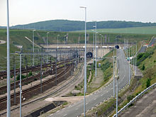 Entrance to the tunnel near Coquelles, France
Eurotunnel Shuttle and Eurotunnel Class 9
Initially 38 Le Shuttle locomotives were commissioned, with one at each end of a shuttle train. The shuttles have two separate halves: single and double deck. Each half has two loading/unloading wagons and 12 carrier wagons. Eurotunnel’s original order was for nine tourist shuttles.
HGV shuttles also have two halves, with each half containing one loading wagon, one unloading wagon and 14 carrier wagons. There is a club car behind the leading locomotive. Eurotunnel originally ordered six HGV shuttle rakes.
Freight locomotives – British Rail Class 92
Forty-six Class 92 locomotives for hauling freight trains and overnight passenger trains (the Nightstar project, which was abandoned) were commissioned, running on both overhead AC and third-rail DC power. However, RFF does not let these run on French railways, so there are plans to certify Alstom Prima II locomotives for use in the tunnel.
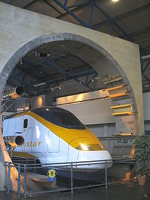
International passenger: British Rail Class 373 and British Rail Class 374
Thirty-one Eurostar trains, based on the French TGV, built to UK loading gauge with many modifications for safety within the tunnel, were commissioned, with ownership split between British Rail, French national railways (SNCF) and Belgian national railways (SNCB). British Rail ordered seven more for services north of London.
At the end of 2009, extensive fire-proofing requirements were dropped and Deutsche Bahn (DB) received permission to run German Intercity-Express (ICE) trains through the tunnel. On 19 October 2010 DB ran the first ICE train through the tunnel, arriving in St Pancras after evacuation tests in the tunnel were a success. Around the same time, Eurostar ordered ten trains from Siemens based on its Velaro product.
Service locomotives
Diesel locomotives for rescue and shunting work are Eurotunnel Class 0001 and Eurotunnel Class 0031.