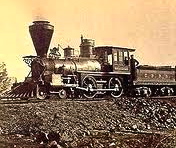
Steam Locomotive Train
The History Of Steam Locomotives
Steam Locomotive Train
 A steam locomotive is a railway locomotive that produces its power through a steam engine. These locomotives are fueled by burning some combustible material, usually coal, wood or oil, to produce steam in a boiler, which drives the steam engine. Both fuel and water supplies are carried with the locomotive, either on the locomotive itself or in wagons pulled behind.
Steam locomotives were first developed in Britain and dominated railway transportation until the middle of the 20th century. From the early 1900s they were gradually superseded by electric and diesel locomotives.
Origins
 Trevithick‘s locomotive, 1804 the first successful steam locomotive
 Stephenson‘s Rocket 1829, the winner of the Rainhill Trials
See also: History of rail transport, Category:Early steam locomotives
The earliest railways employed horses to draw carts along railed tracks.
As the development of steam engines progressed through the 18th century, various attempts were made to apply them to road and railway use. In 1784, William Murdoch, a Scottish inventor, built a prototype steam road locomotive. An early working model of a steam rail locomotive was designed and constructed by steamboat pioneer John Fitch in the United States probably during the 1780s or 1790s. His steam locomotive used interior bladed wheels guided by rails or tracks. The model still exists at the Ohio Historical Society Museum in Columbus.
 The first full-scale working railway steam locomotive was built by Richard Trevithick in the United Kingdom and, on 21 February 1804, the world’s first railway journey took place as Trevithick’s unnamed steam locomotive hauled a train along the tramway from the Pen-y-darren ironworks, near Merthyr Tydfil to Abercynon in south Wales. Accompanied with Andrew Vivian, it ran with mixed success. The design incorporated a number of important innovations that included using high-pressure steam which reduced the weight of the engine and increased its efficiency. Trevithick visited the Newcastle area in 1804 and he had a ready audience of colliery owners and engineers. The visit was so successful that the colliery railways in north-east England became the leading centre for experimentation and development of the steam locomotive. Trevithick continued his own steam propulsion experiments through another trio of locomotives, concluding with the Catch Me Who Can in 1808. Only four years later, the successful twin-cylinder locomotiveSalamanca by Matthew Murray for the edge railed rack and pinion Middleton Railwaydebuted in 1812. In 1825 George Stephenson built the Locomotion for the Stockton and Darlington Railway, north-east England, which was the first public steam railway in the world. In 1829, he built The Rocket which was entered in and won the Rainhill Trials. This success led to Stephenson establishing his company as the pre-eminent builder of steam locomotives used on railways in the United Kingdom, United States and much of Europe. The Liverpool and Manchester Railway opened a year later making exclusive use of steam power for both passenger and freight trains.
The United States started developing steam locomotives in 1829 with the Baltimore and Ohio Railroad‘s Tom Thumb. This was the first locomotive to run in America, although it was intended as a demonstration of the potential of steam traction, rather than as a revenue-earning locomotive. Many of the earliest locomotives for American railroads were imported from Great Britain, including the Stourbridge Lion and the John Bull (still the oldest operable engine-powered vehicle in the United States of any kind, as of 1981) but a domestic locomotive manufacturing industry was quickly established, with locomotives like the DeWitt Clinton being built in the 1830s.
The first railway service in Continental Europe (or for that matter, anywhere outside the United Kingdom and the United States) was opened on 5 May 1835 in Belgium, between Mechelen and Brussels. The name of the locomotive used was The Elephant.
In Germany the first working steam locomotive was a rack-and-pinion engine, similar to the Salamanca, designed by the British locomotive pioneer John Blenkinsop. Built in June 1816 by Johann Friedrich Krigar in the Royal Berlin Iron Foundry (Königlichen Eisengießerei zu Berlin), the locomotive ran on a circular track in the factory yard. It was the first locomotive to be built on the European mainland and the first steam-powered passenger service, because curious onlookers could ride in the attached coaches for a fee. It is portrayed on a New Year’s badge for the Royal Foundry dated 1816. Another locomotive was built using the same system in 1817. They were to be used on pit railways in Königshütte and in Luisenthal on the Saar (today part of Völklingen), but neither could be returned to working order after being dismantled, moved and reassembled. On 7 December 1835 the Adler ran for the first time between Nuremberg and Fürth on the Bavarian Ludwig Railway. It was the 118th engine from the locomotive works of Robert Stephenson and stood under patent protection.
 The Austria, the first locomotive in Austria
In 1837 the first steam railway started up in Austria on the Emperor Ferdinand Northern Railway between Vienna-Floridsdorf and Deutsch-Wagram. The oldest continually working steam engine in the world also runs in Austria: the GKB 671 built in 1860 has never been taken out of service and is still used for special excursions.
In 1838 the third steam locomotive to be built in Germany, the Saxonia, was manufactured by the Maschinenbaufirma Übigau near Dresden, built by Prof. Johann Andreas Schubert. The first independently designed locomotive in Germany was the Beuth built by August Borsig in 1841. In 1848 the first locomotive produced by Henschel-Werke in Kassel, theDrache, was delivered.
The first railway line over Swiss territory was the Strasbourg–Basle line opened in 1844. Three years later, in 1847, the first fully Swiss railway line, the Spanisch Brötli Bahn, from Zürich to Baden was opened.
Basic form

Boiler
Although other types of boiler have been tried both historically and laterally with steam locomotives, their use did not become widespread, and the Firebox Fire-tube boiler has been the dominant source of power in the age of steam locomotion from the Rocket in 1829 to the Mallard in 1938 and beyond.
 A steam locomotive with the boiler and firebox exposed (firebox on the left)
The steam locomotive, when fired up, typically employs a steel firebox fire-tube boiler that contains a heat source to the rear, which generates and maintains a head of steam within the pressurised partially water filled area of the boiler to the front.
The heat source, contained within the firebox, is the energy released by the combustion, typically of a solid or liquid fuel, with the by-product of hot combustion gases. If wood, coal or coke is used as the combustion material it is introduced through a door, typically by a fireman, onto a set of grates where ashes fall away from the burning fuel. If oil is used a door provides for adjusting the air flow, maintenance or for cleaning the oil jets.
The fire-tube boiler is characterised by internal tubes connected to the firebox that guide the smoke and hot combustion gases through the pressurised wet area of the boiler. These tubes greatly increase the contact area between the hot and the wet areas of the boiler and this increases the efficiency of the thermal conduction and thermal radiation processes of heat transfer between the two. The combustion gases emerge from the ends of the fire-tubes at the front of the boiler and are discharged via the smokebox to the chimney (or stack US). Surrounding the boiler layers of insulation or lagging minimise heat loss to the surroundings.
The amount of pressure in the boiler can be monitored by a gauge mounted in the cab and excessive steam pressure can be released manually by the driver or fireman. Alternatively in conditions of high boiler pressure, a safety valve may be triggered to reduce pressure and prevent the boiler violently bursting, which had previously resulted in injuries and fatalities to nearby individuals, as well as extensive damage to the locomotive itself and nearby structures.
 Aftermath of a boiler explosion on a railway locomotive circa 1850.
At the front of the boiler is the smokebox, where used exhaust steam is injected, with the effect of increasing the volume (or draw) of smoke and combustion gases pulled through the fire tubes in the boiler and out through the chimney. Thermal efficiency considerations of a typical fire-tube boiler led Engineers such as Nigel Gresley to consider innovations such as the Water-tube boiler which he trialled on the LNER Class W1, however these designs required a lengthy teething process and there was insufficient will at the time.
The steam generated in the boiler is used to drive the locomotive and also for other purposes (whistles, brakes, pumps, passenger car heating, etc.). The constant use of steam requires the boiler to have water continually pumped into it (usually by automatic means). The source of this water is an unpressurised tank that is usually part of the locomotive’s tender or is wrapped around the boiler in the case of a tank locomotive. Periodic stops are required to refill the water.
During operation, the boiler’s water level is constantly monitored, normally via a transparent tube referred to as a sight glass, or with a gauge. Maintaining a proper water level is central to the efficient and safe operation of the boiler. If the water level is too high, steam production is decreased, efficiency is lost and in extreme cases, water will be carried out with the steam into the cylinders, possibly causing mechanical damage. More seriously, if the water level gets too low, the crown (top) and/or side sheets of the firebox may become exposed. Without sufficient water to absorb the heat of combustion, the firebox sheets may soften and melt, with the possible result of high-pressure steam being ejected with tremendous force through the firebox and into the locomotive’s cab. The development of the Fusible plug to release pressure in conditions of excessively high temperature and low water levels was designed to protect against this occurrence.
Scale may build up in boiler to prevent proper heat transfer, and corrosion will eventually degrade the boiler’s materials to the point where it needs to be rebuilt or replaced. Start-up on a large engine may take hours of preliminary heating of the boiler water before sufficient steam is available.
Although the boiler is typically placed horizontally, for locomotives designed to work in locations with steep slopes, it may be more appropriate to consider vertically or mounted such that the boiler remains horizontal but the wheels are inclined to suit the slope of the rails.
Steam circuit
 The steam generated in the boiler fills the steam space above the water in the partially filled boiler. Its maximum working pressure is limited by spring-loaded safety valves. It is then collected either in a perforated tube fitted above the water level or from a dome that often houses the regulator valve, or throttle, the purpose of which is to control the amount of steam leaving the boiler. The steam then either travels directly along and down a steam pipe to the engine unit or may first pass into the wet header of a superheater, the role of the latter being to improve thermal efficiency and eliminate water droplets suspended in the “saturated steam”, the state in which it leaves the boiler. On leaving the superheater, the steam exits the dry header of the superheater and passing down a steam pipe entering the steam chests adjacent to the cylinders of a reciprocating engine. Inside each steam chest is a sliding valve that distributes the steam via ports that connect the steam chest to the ends of the cylinder space. The role of the valves is twofold: admission of each fresh dose of steam and exhaust of the used steam once it has done its work.
The cylinders are double acting, with steam admitted to each side of the piston in turn. In a two-cylinder locomotive, one cylinder is located on each side of the locomotive. The cranks are set 90° out of phase. During a full rotation of the driving wheel, steam provides four power strokes; each cylinder receives two injections of steam per revolution. The first stroke is to the front of the piston and the second stroke to the rear of the piston; hence two working strokes. Consequently two deliveries of steam onto each piston face in two cylinders generates a full revolution of the driving wheel. Each piston is connected to the driving axle on each side by a connecting rod, the driving wheels are connected together by coupling rods to transmit power from the main driver to the other wheels. Note that at the two “dead centres“, when the connecting rod is on the same axis as the crankpin on the driving wheel, the connecting rod applies no torque to the wheel. Therefore, if both cranksets could be at “dead centre” at the same time, and the wheels should happen to stop in this position, the locomotive could not be started moving. Therefore the crankpins are attached to the wheels at a 90° angle to each other, so only one side can be at dead centre at a time.
Each piston transmits power directly through a connecting rod (US: main rod) and a crankpin (US: wristpin) on the driving wheel (US main driver) or to a crank on a driving axle. The movement of the valves in the steam chest is controlled through a set of rods and linkages called the valve gear, actuated from the driving axle or else from the crankpin; the valve gear includes devices that allow reversing the engine, adjusting valve travel and the timing of the admission and exhaust events. The cut-off point determines the moment when the valve blocks a steam port, “cutting off” admission steam and thus determining the proportion of the stroke during which steam is admitted into the cylinder; for example a 50% cut-off admits steam for half the stroke of the piston. The remainder of the stroke is driven by the expansive force of the steam. Careful use of cut-off provides economical use of steam and, in turn, reduces fuel and water consumption. The reversing lever (US: Johnson bar), or screw-reverser (if so equipped), that controls the cut-off therefore performs a similar function to a gearshift in an automobile – maximum cut-off, providing maximum tractive effort at the expense of efficiency, is used to pull away from a standing start, whilst a cut-off as low as 10% is used when cruising, providing reduced tractive effort with lower fuel/water consumption.
 Walschaerts valve gear in a steam locomotive. In this animation, the red colour represents live steam entering the cylinder, blue represents expanded (spent) steam being exhausted from the cylinder. Note that the cylinder receives two steam injections during each full rotation; the same occurs in the cylinder on the other side of the engine.
Exhaust steam is directed upwards to the atmosphere through the chimney, by way of a nozzle called a blastpipe that gives rise to the familiar “chuffing” sound of the steam locomotive. The blastpipe is placed at a strategic point inside the smokebox that is at the same time traversed by the combustion gases drawn through the boiler and grate by the action of the steam blast. The combining of the two streams, steam and exhaust gases, is crucial to the efficiency of any steam locomotive, and the internal profiles of the chimney (or, more strictly speaking, the ejector) require careful design and adjustment. This has been the object of intensive studies by a number of engineers (and almost totally ignored by others with sometimes catastrophic effect). The fact that the draught depends on the exhaust pressure means that power delivery and power generation are automatically self-adjusting. Among other things, a balance has to be struck between obtaining sufficient draught for combustion whilst giving the exhaust gases and particles sufficient time to be consumed. In the past, fierce draught could lift the fire off the grate, or cause the ejection of unburnt particles of fuel, dirt and pollution for which steam locomotives had an unenviable reputation. Moreover, the pumping action of the exhaust has the counter effect of exerting back pressure on the side of the piston receiving steam, thus slightly reducing cylinder power. Designing the exhaust ejector has become a specific science in which Chapelon, Giesl and Porta were successive masters, and it was largely responsible for spectacular improvements in thermal efficiency and a significant reduction in maintenance time and pollution. A similar system was used by some early gasoline/kerosene tractor manufacturers (Advance-Rumely/Hart-Parr) – the exhaust gas volume vented through a cooling tower meant that the steam exhaust helped draw more air past the radiator.
Running gear

Steam-cleaning the running gear of an “H” class locomotive, Chicago and North Western Railway, 1943

Running gear of steam locomotive.
This includes the brake gear, wheel sets, axleboxes, springing and the “motion” that includes connecting rods and valve gear. The transmission of the power from the pistons to the rails and the behaviour of the locomotive as a vehicle, able to negotiate curves, points and irregularities in the track is of paramount importance. Because reciprocating power has to be directly applied to the rail from 0 rpm upwards, this poses unique problems of “adhesion” of the driving wheels to the smooth rail surface. Adhesive weight is the portion of the locomotive’s weight bearing on the driving wheels. This is made more effective if a pair of driving wheels is able to make the most of its “axle load”, i.e., its individual share of the adhesive weight. Locomotives with “compensating levers” connecting the ends of plate springs have often been deemed a complication but locomotives fitted with them have usually been less prone to loss of traction due to wheel-slip.
Locomotives with total adhesion, i.e., where all the wheels are coupled together, generally lack stability at speed. This makes desirable the inclusion of unpowered carrying wheel smounted on two-wheeled trucks or four-wheeled bogies centred by springs that help to guide the locomotive through curves. These usually take the weight of the cylinders in front or of the firebox at the rear end when the width of this exceeds that of the mainframes. For multiple coupled wheels on a rigid chassis a variety of systems for controlled side-play exist.
Railroads typically wanted a locomotive with as few axles as possible. This would reduce the cost of maintenance. The number of axles required was dictated by the maximum axle loading of the railroad in question. A builder would typically add axles until the maximum weight on any one axle was acceptable to the railroad’s maximum axle loading. A locomotive with a wheel arrangement of two lead axles, two drive axles, & one trailing axle was in actuality a high speed machine. Two lead axles were necessary to have good tracking at high speeds. Two drive axles had a lower reciprocating mass than three, four, five, or six coupled axles. They were thus able to turn very high speeds due to the lower reciprocating mass. A trailing axle was able to support a huge firebox. Hence most locomotives with the wheel arrangement of 4-4-2 (American Type Atlantic) were “free steamers” able to maintain steam pressure regardless of throttle setting.